
Railway systems rely on electrical power for traction, signaling, communications, stations, and essential infrastructure. High-energy equipment operates continuously throughout the network, making electrical safety critical. Implementing reliable high voltage grounding provides a controlled path for fault current, protecting railway workers, equipment, passengers, and daily operations when electrical faults strike.
Key Takeaways
- Divert high fault currents: Direct lethal energy straight into the earth grid before it energizes metal enclosures.
- Reduce touch and step potentials: Maintain safe voltage thresholds across ballast, walkways, and trackside equipment during line-to-ground faults.
- Trip protective relays reliably: Ensure rapid circuit breaker interruption by maintaining predictable ground-fault loop impedances.
- Control traction return paths: Isolate stray currents to prevent severe galvanic corrosion on adjacent rail ties and structural steel.
- Protect sensitive electronics: Shield delicate signaling systems and track circuits from transient high-voltage surges.
Why Is Grounding Critical in Railway Systems?
Railway electrical infrastructure handles massive voltage and current levels across substations, overhead catenary lines, third rails, switchgear, and track signaling networks. When a ground fault occurs without a low-impedance path, current follows unintended routes. Metal enclosures develop lethal potentials, creating severe safety risks and triggering catastrophic equipment failure.
- Protecting Railway Personnel - Field technicians, contractors, track crews, and emergency teams regularly inspect energized infrastructure. High voltage grounding establishes equipotential bonding so exposed metal components remain at safe voltage levels, preventing severe shocks during maintenance or emergency response operations.
- Protecting Electrical Equipment - Transformers, switchgear, and signaling controllers face severe mechanical and thermal stress during ungrounded fault conditions. Proper grounding routes fault currents in predictable ways, working alongside surge arresters and breakers to isolate insulation failures, lightning strikes, and switching surges.
- Supporting Reliable Railway Operations - Uncontrolled electrical faults ruin sensitive signaling equipment, stall trains, and force expensive track closures. Engineered ground systems provide immediate fault detection, allowing protective relays to trip instantly and limit downtime across wide rail networks.
How Does Grounding Affect Railway Traction Power?
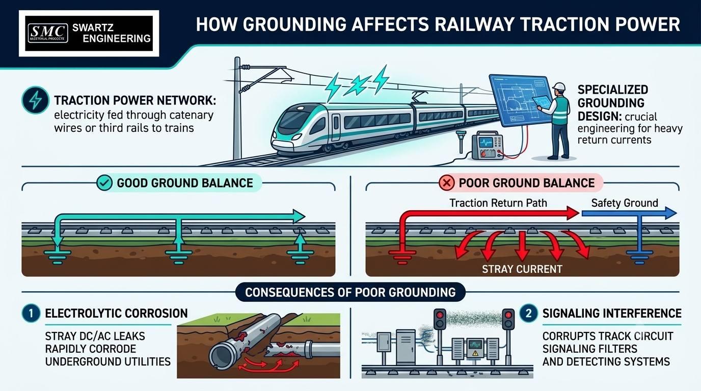
Traction power networks feed electricity to moving trains through overhead catenary wires or third rails, requiring specialized grounding designs. Engineers must account for heavy running current returning through the tracks while managing stray direct current (DC) or alternating current (AC) leaks that degrade surrounding infrastructure.
The reality on the ground is that traction return paths share space with safety grounds. Poorly balanced grounding allows stray current to escape into surrounding soil, eating away underground utility pipes through rapid electrolytic corrosion and corrupting track circuit signaling filters.
GET IN TOUCH
The ultimate solution for reliable power control! call us at 276-285-3841
What Are Touch and Step Voltages?
Touch voltage measures the potential difference between a grounded metal structure and a person's hand during a fault, while step voltage measures the potential between a person's feet. High fault currents flowing into the soil create voltage gradients across the surface, requiring ground grid design to keep these differences safe.
Managing touch and step voltage requires careful ground grid spacing, soil resistivity testing, crushed-rock surface layers, and equipotential bonding paths. Swartz Engineering calculates these specific parameters to eliminate dangerous voltage spikes around trackside cabinets and substation perimeters.
Why Is Railway Grounding More Than a Ground Rod?
A simple ground rod cannot handle the high fault currents, variable soil conditions, and complex return paths of modern transit systems. Comprehensive protection demands ground mats, structural bonding, buried counterpoise wires, and low-impedance connections custom-engineered for local soil conditions.
Grounding systems must account for seasonal soil moisture variations, freezing depths, and high soil resistivity. Driving a single copper rod into dry sand or rocky soil won't protect expensive gear during a 20kA fault.
What Should Railway Operators Consider When Planning Grounding?
Designing an effective ground system requires evaluating both electrical and physical environment variables:
- System Operating Voltage: High-voltage AC and DC traction systems demand specialized isolation and grounding approaches.
- Maximum Available Fault Current: Ground conductors must be sized properly to handle severe thermal stresses without melting.
- Localized Soil Resistivity: In-situ soil testing determines grid density and deep-well grounding needs.
- Traction Current Return Paths: Isolated negative return paths must be balanced against safety ground bonding.
- Substation and Equipment Layout: Dense trackside switchgear placement requires continuous equipotential planes.
- Public and Personnel Access Points: High-traffic stations and passenger platforms require strict touch voltage limits.
- Structural Equipotential Bonding: Catenary portals, bridges, and passenger sheds must be bonded directly into the grid.
- Protective Relay Coordination: Low ground loop impedance ensures overcurrent devices clear faults instantly.
- Industry Standards Compliance: Systems must meet strict IEEE 80, IEEE 81, and AREMA safety specifications.
Step-by-Step System Implementation
- Perform In-Situ Soil Testing
- Execute four-pin Wenner soil resistivity surveys across all substation footprints and track corridors.
- Map multi-layer soil profiles to account for seasonal moisture changes and freeze-thaw cycles.
- Calculate Ground Grid Geometry
- Model touch and step potential limits using actual system short-circuit fault levels.
- Size ground grid conductors and copper ground rods to handle projected thermal stresses.
- Install Equipotential Bonding Networks
- Connect all non-current-carrying metal enclosures, structural steel, and catenary poles to the ground grid.
- Place crushed stone layers across high-voltage areas to increase foot-contact surface resistance.
- Verify Protection Device Coordination
- Measure final ground resistance using the fall-of-potential method before energizing.
- Confirm that ground loop impedance allows protective relays to trip immediately during a fault.
How Do Custom Ground Systems Compare to Generic Setup?
|
|
|
|
|
|
|
|
|
|
|
|
|
|
|
|
|
|
|
|
|
|
|
|
Critical System Infrastructure Elements
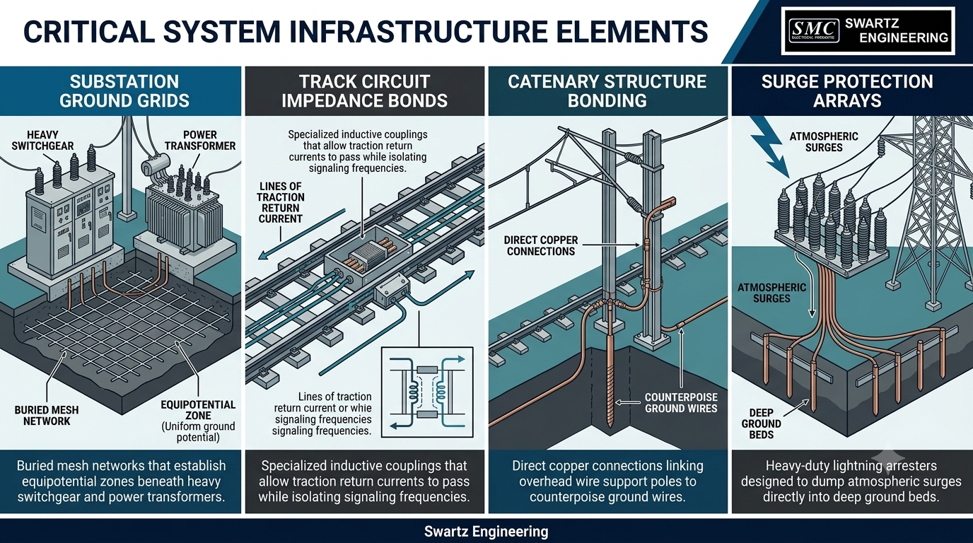
- Substation Ground Grids: Buried mesh networks that establish equipotential zones beneath heavy switchgear and power transformers.
- Track Circuit Impedance Bonds: Specialized inductive couplings that allow traction return currents to pass while isolating signaling frequencies.
- Catenary Structure Bonding: Direct copper connections linking overhead wire support poles to counterpoise ground wires.
- Surge Protection Arrays: Heavy-duty lightning arresters designed to dump atmospheric surges directly into deep ground beds.
GET IN TOUCH
The ultimate solution for reliable power control! call us at 276-285-3841
Real-World Field Insight: Preventing Stray Current Corrosion
Field Tip: In DC transit systems, blindly grounding negative return rails to structural ground grids can ruin nearby infrastructure. Current will flow through moist soil, corroding utility mains, bridge rebar, and rail fasteners. Always install specialized diode grounding devices or voltage-limiting devices (VLDs). These keep rails isolated during normal operation while instantly bonding them to ground during fault conditions.
How Does Swartz Engineering Support Railway Electrical Infrastructure?
Swartz Engineering delivers practical engineering solutions for railway traction power, distribution systems, and grounding infrastructure across the USA. Our team designs, builds, and evaluates system-wide electrical protection to ensure your railway operates safely and reliably under all operating conditions.
Ready to Secure Your Railway Power Infrastructure?
Inadequate grounding puts field personnel, expensive traction equipment, and service schedules at risk. Swartz Engineering provides specialized expertise in power distribution, system protection, and grounding analysis across the United States. Contact our engineering team today to review your project requirements and strengthen your high voltage grounding infrastructure.
Frequently Asked Questions
Q: What Is The Main Purpose Of High Voltage Grounding?
A: High voltage grounding provides a controlled path for fault current, preventing lethal voltages on metal structures. It lowers dangerous touch and step potentials around equipment and ensures protective relays trip instantly during line-to-ground faults.
Q: Why Is Grounding Important For Railway Safety?
A: Railways run high-energy electrical systems near personnel, passengers, and public infrastructure. Engineered grounding manages fault currents safely, protecting workers during maintenance and preventing shock hazards on trackside metal structures.
Q: Does Railway Grounding Only Involve Ground Rods?
A: No, complete railway grounding relies on ground grids, bonding cables, counterpoise wires, and return path controls. A single ground rod cannot handle high short-circuit currents or compensate for high soil resistivity.
Q: What Are Touch And Step Voltages?
A: Touch voltage is the electrical potential between a grounded object and a person touching it, while step voltage occurs between a person's feet. Both measure voltage differences across the earth during a fault and must be kept within safe limits.
Q: Can Poor Grounding Affect Railway Operations?
A: Yes, poor grounding causes false signaling trips, damages switchgear, accelerates rail corrosion, and triggers unscheduled system shutdowns. Proper ground system design provides predictable fault clearing to keep trains running reliably.
Products We Offer
Swartz Engineering strives to provide top-quality products to achieve our customer's needs. Our products include:
- Type 76 DC Relay
- Type 82 DC Relay
- Swartz Engineering’s Type 64 Ground Relay
- Type 32 Reverse Current Relay
- Type 150 DC
- CSM Shield Monitor
- Metal Oxide Surge Arrestors
- Transducers
- MVIS SL Slim-line Contactor
- Fully-tested Power Control Rooms
- Swartz Engineering’s Portable Substations
For nearly half a century, we have proudly led the industry in ensuring safety and efficiency. Swartz Engineering is a trusted family-owned company dedicated to providing top-notch power distribution solutions for the electrical industry. Contact us today.