Superior Protection with Type 32 Reverse Current Relay
GET IN TOUCH
Take the first step towards safeguarding your operations! call us at 276-285-3841
General
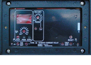
The Swartz Type 32 Reverse Current Relay is an isolated current monitor which is used with either the positive or negative conductors in D.C. power distribution networks. The primary function of the detector is to monitor low levels of reverse feeder current. All front panel controls are calibrated in millivolts so that the detector can be used with any shunt.
Test
A built-in calibration control (CAL) with variable settings from 0 to 20 mV and a momentary pushbutton switch (TEST) allow functional check of reverse threshold. Test current can be read on the meter or at “SIG OUT” test jacks where 0.5V at test jacks equals 50mV at shunt. Test current adds to any current already present at shunt leads.
Digital Meter
The meter reads from 0 to 20mV
Power
The green light emitting diode (LED) indicates that the detector has power and is operational. If this LED is off, either input power is off or internal 1 A fuse is blown. In either case, the output is fail safe and should cause substation trip.

CALL US TODAY
Learn more about our products with our experts
Zero
This adjustment compensates for slight offsets in the high voltage isolator and should only require adjustment when the overcurrent unit is initially installed in the substation. With zero shunt current (DC breaker open or zero loads) measure “SIG OUT” voltage with a Fluke 8024A digital voltmeter or equal. Adjust zero for .000 + .002 volts. For best results, a five minute or greater warm-up period should be allowed. Note that offset varies slightly depending on installation. For example, offset will change by up to 1mV when the detector is bench tested outside of its enclosure.
Instant Overcurrent Channel
This channel responds to reverse “instantaneous” current levels between 0 and 20mV as set by the control. Input from the isolator is RC filtered so that current spikes or noise are suppressed to prevent nuisance tripping. A buffered test jack is provide for highly accurate adjustment of trip threshold with a digital voltmeter. A red LED latches on to indicate that a trip has occurred.
Setting “Pickup” Threshold
Connect digital voltmeter common lead to “SIG OUT-COM”. Connect positive lead (+) to instant test jack. Using the 200mV range on the DVM, adjust pickup control for desired trip level. Note that knob calibration for this control is only approximate (+10%). As an alternate method of setting this control, apply trip level to shunt leads or by using “CAL/TEST” controls. While pressing CAL/TEST switch adjust PICKUP knob until instant LED is just turned on. Press RESET to reset LED
Get the full details in the product sheet below
CONTACT US TODAY
Take the first step towards powering up your operations! call us at 276-285-3841